Why Choose a Single Gauge Manifold?
Choosing the right pressure measurement arrangement affects accuracy, maintenance, and operator confidence. A Single Gauge Manifold offers a compact connection between a pressure gauge and the process line. Its valves can help isolate the instrument during inspection, calibration, or replacement. This simple layout may reduce tubing, fittings, and potential leak points.
Space matters. In a crowded control panel, a compact manifold leaves room for transmitters and cable routes. Fewer connections can also make visual inspections easier. An engineer can check valve positions, thread condition, and signs of leakage without removing surrounding equipment. However, compact does not mean automatically safer or more accurate. The manifold must match the process medium, pressure range, temperature, connection type, and gauge requirements.
Reliable selection depends on practical evidence. Review the manufacturer’s pressure ratings and material data before installation. Confirm that sealing methods suit the process and operating temperature. Calibration records should remain traceable to recognized standards. They support dependable readings during maintenance and technical reviews. Small details matter.
A Single Gauge Manifold is not always the perfect choice. Systems requiring differential pressure measurement, frequent venting, or complex calibration may need a different configuration. That limitation deserves honest attention. Poor valve access can delay maintenance, while incorrect installation can distort readings or create avoidable hazards. Experienced technicians assess the full application, not just the purchase price. When simplicity, accessibility, and reliable isolation are priorities, this manifold design can provide a practical and disciplined solution.
Single-Gauge Manifolds: Definition, Ports, and Core Functions
Why Choose a Single Gauge Manifold?
Single-Gauge Manifolds: Definition, Ports, and Core Functions
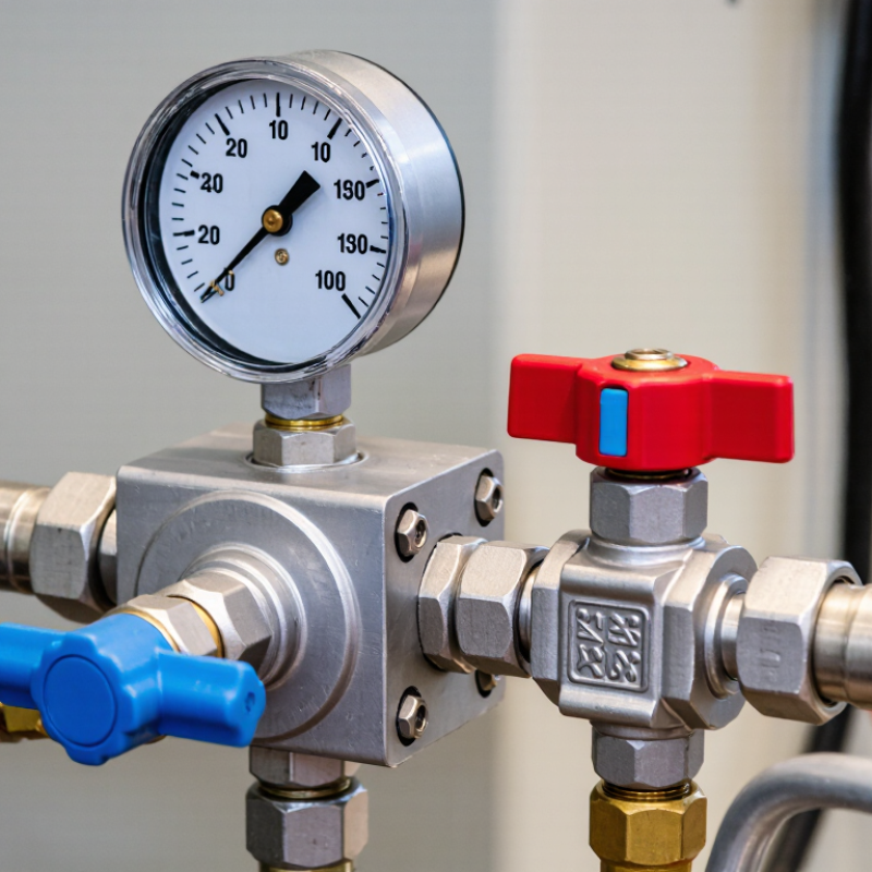
A single gauge manifold is a compact fluid-control assembly with one pressure gauge. It connects a supply line, equipment line, and pressure-monitoring point. The manifold body directs flow through internal passages. The gauge displays pressure in one selected section. It is simple to read. That simplicity matters in cramped panels and field service work.
Typical ports include an inlet, outlet, gauge connection, and sometimes a vent or drain port. Port locations vary by design, so technicians should check the flow markings carefully. The inlet receives fluid from the source. The outlet sends it toward connected equipment.
A vent port can help release trapped pressure during maintenance, when the system design permits it. Thread quality and seal selection require attention.
The core functions are isolation, monitoring, and controlled routing.
Closing the valve can separate equipment from the supply. Opening it can restore flow after inspection. In practice, a single gauge manifold reduces visual clutter and lowers installation effort. I have found it useful where only one pressure zone needs regular observation. However, it cannot show two pressures at once. That limitation is easy to overlook. A pressure reading may also become misleading if the gauge is installed on the wrong side of the isolation valve. Careful labeling, leak checks, and gradual valve operation improve reliability. The design is efficient, but not automatically suitable for every system.
ASME B40.100: Grade A Gauges Deliver ±0.5% Span Accuracy
Why Choose a Single Gauge Manifold?
ASME B40.100: Grade A Gauges Deliver ±0.5% Span Accuracy
A single gauge manifold can make pressure readings easier to monitor and interpret. Under ASME B40.100, Grade A gauges provide accuracy within ±0.5% of span. Span means the difference between the gauge’s lower and upper measurement limits. For a 0–100 psi gauge, the possible accuracy error is approximately ±0.5 psi across the scale.
That level of precision supports controlled testing, calibration checks, and routine process monitoring. It also reduces uncertainty when operators compare readings from connected systems.
A clear dial helps. So does proper valve arrangement. Technicians should still confirm the pressure range before installation. A highly accurate gauge can perform poorly when exposed to vibration, pulsation, or unsuitable temperature.
Installation details matter more than many teams expect. Keep the manifold accessible, protect the sensing element, and inspect connections for leakage. Calibration records should identify the instrument, test conditions, and reference standard. These details support traceability and demonstrate professional control.
Accuracy is not perfection. That distinction deserves attention. A Grade A gauge may meet ±0.5% span accuracy, yet poor positioning can distort the practical reading. I have seen specifications receive more attention than installation conditions. That is an easy mistake. Selecting one manifold with a properly matched Grade A gauge creates a more consistent measurement point, but regular verification remains necessary.
Installation Efficiency: Fewer Connections Reduce Potential Leak Paths
Why Choose a Single Gauge Manifold?
Installation efficiency is a practical reason to choose a single gauge manifold. Every additional tube, adapter, and fitting creates another potential leak path. Fewer connections usually mean fewer assembly errors and less inspection time. The U.S. Department of Energy reports that compressed-air leaks can waste 20% to 30% of compressor output. Although instrumentation systems differ, the lesson is similar: small leakage points can create measurable operating losses. In field installations, a compact manifold also reduces tubing clutter around the gauge. That makes pressure readings easier to verify.
Fewer joints help technicians work faster. A single manifold can combine isolation, venting, and pressure measurement in one controlled assembly. This reduces repeated cutting and retightening during maintenance. It also makes leak testing more consistent. The Energy Institute’s Process Safety Performance Indicators guidance stresses the value of reliable, preventive inspection data. A simpler connection layout supports that discipline. However, fewer connections do not guarantee zero leaks. Poor tightening, vibration, contamination, or unsuitable seals can still cause failure. That detail is easy to underestimate.
Tips: Confirm the pressure rating before installation. Keep tubing clean and supported. Mark each valve clearly. Perform a documented leak test after assembly. Recheck connections after the system reaches operating temperature. A short checklist prevents long troubleshooting sessions.
Why Choose a Single Gauge Manifold?
Installation Efficiency: Fewer Connections Reduce Potential Leak Paths
This representative connection-count model assumes two process connections for each separately mounted gauge, while a shared manifold uses one common inlet, one common outlet, and one gauge connection per instrument. Fewer interfaces can simplify installation and reduce the number of potential leak paths.
Selection Criteria: Pressure Range, Temperature, Media, and Materials
Why Choose a Single Gauge Manifold?
A single gauge manifold combines pressure measurement and control in one compact assembly. It can reduce tubing, leak points, and installation time. The correct choice depends on operating conditions, not appearance alone. Start with the pressure range. A gauge should operate near the middle of its scale, where readings are clearest. Oversizing can reduce resolution, while a narrow range may cause damage during pressure spikes.
Temperature is equally important. Check both the process temperature and the surrounding environment. Hot fluids may require cooling sections or remote mounting. Sudden temperature changes can also affect accuracy.
Media compatibility must be verified carefully. Water, oil, gas, corrosive chemicals, and oxygen service can require different internal designs. Never assume a familiar fluid is harmless to every seal or connection.
Tips:
Match wetted materials with the actual media, not its common name. Stainless steel may suit many applications, but seals, seats, and gauge internals still need review. Consider pressure surges, vibration, and maintenance access.
A manifold that works well on a test bench may be awkward beside a vibrating pump. This is often overlooked.
Review the material certificate, temperature limits, pressure rating, and cleaning requirements with a qualified engineer.
No selection method is perfect. Real installations sometimes reveal assumptions that drawings missed. Keep a small margin for those surprises.