What Is a Large CNC Machine and How Does It Work?

What Is a Large CNC Machine and How Does It Work?

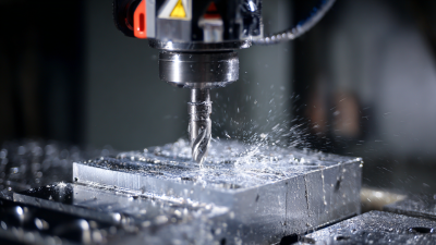
A large cnc machine is an industrial computer-controlled system built to cut, drill, mill, or shape oversized materials. It commonly handles steel plates, aluminum structures, aerospace parts, molds, and heavy equipment components. Unlike a small workshop router, it needs a rigid frame, powerful motors, long travel distances, and careful vibration control.

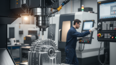
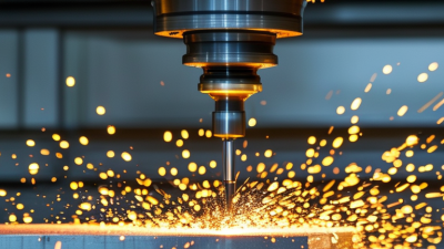
John T. Parsons, a pioneer of numerical control, described its importance by saying, “The NC machine is the first step in the automation of the machine tool industry.” His statement still explains the basic idea. An operator prepares a digital design and converts it into machine instructions. The controller then guides each axis with programmed accuracy. Cutting tools move along the X, Y, and Z axes, while coolant reduces heat near the cutting edge.

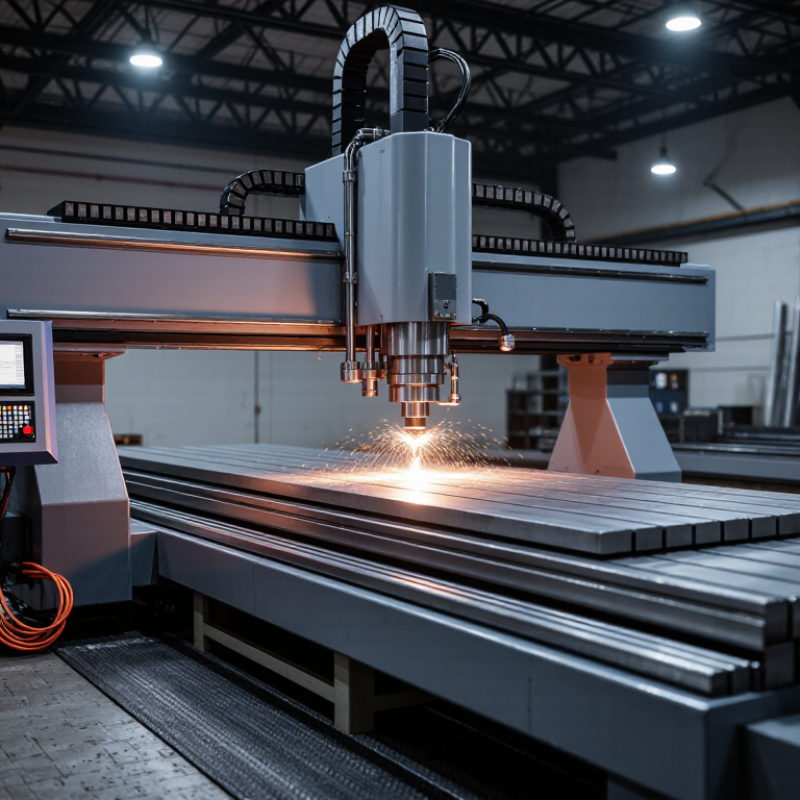
The scale becomes obvious on the shop floor. A gantry may span several meters. A steel workpiece can weigh hundreds of kilograms. Even a small programming error may damage an expensive tool or produce unusable parts. That risk makes setup, calibration, workholding, and operator experience essential.

However, size does not automatically mean better performance. A poorly aligned large cnc machine can create taper, chatter, or uneven surfaces. This is where the topic becomes less simple than it first appears. Speed, accuracy, material, and maintenance must work together. In the sections ahead, we will examine the machine’s main components, operating process, advantages, limitations, and practical selection considerations.
What Is a Large CNC Machine and How Does It Work?

Definition and Core Features of a Large CNC Machine

What Is a Large CNC Machine and How Does It Work?

Definition and Core Features of a Large CNC Machine

A large CNC machine is defined by its work envelope, load capacity, and structural reach. There is no universal dimensional cutoff. A 2024 market analysis by Grand View Research estimated the global CNC machine market at about USD 88 billion in 2023. This growth reflects demand for automated, repeatable metal processing across heavy manufacturing.

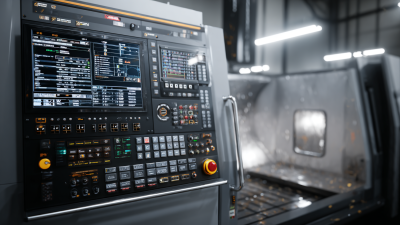
The machine reads CAD/CAM instructions and converts them into controlled axis movements. Servo motors drive the table, gantry, or cutting head. Encoders provide feedback during operation. Large models often use bridge or gantry structures, high-torque spindles, reinforced beds, and multi-axis control. These features support large plates, frames, molds, and fabricated components. A typical cutting cycle may include roughing, finishing, tool changes, coolant delivery, and chip evacuation. It is a coordinated process.

Accuracy is not created by size alone. Thermal expansion, foundation vibration, tool wear, and poor fixturing can reduce final precision. ISO 230-1 provides principles for testing machine-tool geometric accuracy, while practical inspection may include laser measurement and ball-bar testing. The International Federation of Robotics reported 541,302 industrial robots installed worldwide in 2023, showing how strongly factories are adopting automated production systems. However, a large CNC machine still needs skilled setup and inspection. Bigger is not automatically better. In some workshops, the label “large” remains too vague. Defining travel, payload, tolerance, and material type gives a more reliable specification.

Main Components and Their Roles

What Is a Large CNC Machine and How Does It Work?

A large CNC machine uses computer instructions to cut, drill, or shape oversized materials. Its rigid frame supports heavy workpieces and reduces vibration during machining. The worktable holds the material firmly, while linear guides move cutting tools with controlled accuracy. Servo motors drive these movements through ball screws or other motion systems.

A controller reads the programmed toolpath and coordinates every axis. Small errors can still appear. Heat, dust, and poor alignment affect real results.

Main Components and Their Roles

The spindle rotates the cutting tool at a selected speed and delivers machining power. Tool holders connect cutters to the spindle and must remain clean and properly tightened. The tool magazine stores different cutters, allowing automatic changes between operations.

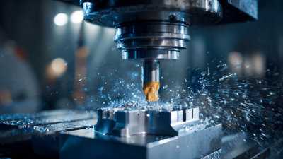
Coolant systems reduce heat, remove chips, and improve surface quality. However, excessive coolant may hide a developing mechanical problem. Operators should check flow, pressure, and contamination regularly.

The machine bed carries the structure and absorbs cutting forces. Enclosures protect operators from chips and contain coolant during production. Sensors monitor position, temperature, and operating conditions. These signals help the control system correct movement or stop unsafe operation.

Before machining, technicians inspect clamping, tool wear, and program coordinates. A measured setup is safer than trusting software alone. Even experienced users occasionally miss a small offset. That mistake can ruin material quickly.

How Computer Numerical Control Directs Machine Movement

What Is a Large CNC Machine and How Does It Work?

A large CNC machine uses computer numerical control to move cutting tools with measured precision. Its working area may handle long beams, thick plates, or oversized wooden panels. The process begins with a digital drawing. CAM software converts that design into toolpaths and coded instructions, often called G-code. The controller reads each command and coordinates movement across several axes.

Each axis has a motor, drive system, and position sensor. The controller sends electrical signals to the motors, while encoders report the actual position. If movement differs from the programmed path, the control system can correct it.

This feedback matters when a heavy gantry accelerates or changes direction. Even a small error can affect hole locations or surface quality.

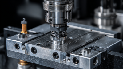
The spindle rotates the cutting tool at a selected speed. Feed rate, tool diameter, material hardness, and cutting depth must work together. Operators also secure the workpiece carefully because vibration can damage both the part and the tool.

A practical shop-floor lesson is that accurate code cannot fix poor setup.

Large machines also need clean rails, calibrated axes, and regular inspection. I have found that “automatic” does not mean unattended. Heat, dust, tool wear, and imperfect measurements still influence results. That limitation deserves attention, especially when a first test cut looks correct but later passes drift.

Step-by-Step Process of Large-Scale CNC Machining

What Is a Large CNC Machine and How Does It Work?

Large-scale CNC machining begins with a digital model, not a cutting tool. Engineers review material, tolerances, and machine travel before programming begins. Grand View Research valued the global CNC machine market at approximately $83.99 billion in 2023. This growth reflects demand for accurate, repeatable production.

The process starts when CAD geometry becomes CAM toolpaths. Programmers select cutting speeds, feed rates, and tools for each surface. Operators then clean the table and secure the workpiece with heavy-duty fixtures. A small alignment error can ruin a large component. It happens more often than people admit. Probing systems measure the stock position and transfer corrections to the controller.

Roughing removes excess metal with deep passes. Coolant carries heat and chips away from the cutting zone. Finishing follows with lighter passes, creating smoother walls and tighter dimensions. The machine may pause for tool changes or additional probing. After machining, inspectors check critical features using portable arms, gauges, or coordinate measuring machines. Deloitte’s 2024 Smart Manufacturing and Operations Survey found that 86% of manufacturers viewed smart manufacturing as important for future competitiveness. That supports real-time monitoring, but automation does not replace judgment. Warped stock, vibration, or a dull tool can still produce unexpected results. Careful inspection remains essential.

What Is a Large CNC Machine and How Does It Work? — Step-by-Step Process of Large-Scale CNC Machining
Step Data Dimension Typical Data or Specification How It Applies to Large-Scale CNC Machining Typical Output or Control Point
1 Machine Definition A computer-controlled machining system designed for large workpieces, long components, or high material-removal requirements. The machine uses programmed tool paths to control cutting tools along multiple linear and rotary axes. Repeatable production of large, complex, and dimensionally controlled parts.
2 Typical Working Envelope Approximately 2,000–20,000 mm in X-axis travel, 1,000–5,000 mm in Y-axis travel, and 800–3,000 mm in Z-axis travel, depending on machine configuration. The work envelope determines the maximum part size that can be machined without repositioning or using multiple setups. Suitable capacity for molds, structural components, energy equipment, transportation parts, and large plates.
3 Machine Configuration Common configurations include gantry, bridge, double-column, horizontal, vertical, and five-axis machining centers. The machine structure is selected according to part geometry, access requirements, workpiece weight, and required rigidity. Improved access to large surfaces and better support during heavy cutting.
4 Number of Controlled Axes Three-axis systems control X, Y, and Z movement. Four- and five-axis systems add rotary or tilting motion. Additional axes allow the cutting tool to approach angled surfaces and reduce the number of workholding setups. Higher geometric flexibility and fewer alignment errors between operations.
5 Workpiece Weight Capacity Typical large-machine tables may support several tonnes; heavy-duty systems can support substantially more. The table, foundation, linear guides, and drive system must safely handle both static workpiece weight and cutting forces. Stable machining with reduced vibration and controlled deformation.
6 Engineering Input A 2D drawing, 3D CAD model, material specification, tolerance requirements, and inspection criteria. Manufacturing engineers review geometry, datum references, machining allowances, tool access, and clamping locations. An approved manufacturing plan and clearly defined inspection requirements.
7 Material Preparation Common materials include carbon steel, stainless steel, aluminum alloys, cast iron, titanium alloys, plastics, and composites. The raw stock is cut or prepared with sufficient machining allowance and checked for material identity and condition. A traceable workpiece ready for secure loading and setup.
8 Fixturing and Alignment Heavy-duty fixtures, modular tooling, clamps, support blocks, pallets, or vacuum systems may be used. The workpiece is positioned from established datums, clamped securely, and aligned using probing or precision measurement equipment. A stable setup with known work coordinates and minimized movement during cutting.
9 CAM Programming Computer-aided manufacturing software converts the CAD model into tool paths and machine-readable numerical control code. The programmer defines tools, cutting strategies, coordinate systems, speeds, feeds, stepovers, and machining sequences. A verified NC program prepared for simulation and machine transfer.
10 Tool Selection Typical tools include face mills, end mills, drills, reamers, boring tools, thread mills, and form tools. Tool geometry and coating are selected according to material, operation type, required surface finish, and cutting load. Appropriate cutting performance, tool life, and dimensional stability.
11 Rough Machining High material-removal operations leave a controlled allowance for later finishing; cutting parameters vary by material and tool size. The machine removes bulk material using strategies such as adaptive milling, pocketing, drilling, or heavy facing. Reduced stock with controlled heat, vibration, and tool loading.
12 Semi-Finishing A smaller and more consistent machining allowance is left on critical surfaces, commonly around 0.2–1.0 mm depending on the part. Semi-finishing corrects roughing variation and prepares surfaces for consistent finishing cuts. More uniform stock distribution and improved dimensional control.
13 Finishing Machining Finishing operations use lighter cuts, smaller stepovers, and controlled feeds to achieve the required form and surface quality. The machine completes critical profiles, bores, holes, sealing surfaces, pockets, and contoured areas. Typical machined-part tolerances may range from approximately ±0.01 to ±0.10 mm, depending on size, material, process, and inspection method.
14 Coolant and Chip Management Flood coolant, through-tool coolant, air blast, or minimum-quantity lubrication may be used. Cooling and chip evacuation control cutting temperature, reduce tool wear, and prevent chips from being recut. More stable cutting conditions and improved surface consistency.
15 In-Process Measurement Touch probes, tool setters, laser measurement, and electronic gauging can verify positions and tool condition. Measurements are taken during production to update work offsets, detect tool wear, and confirm critical features. Reduced setup errors, less scrap, and better process repeatability.
16 Large-Part Deformation Control Thermal growth, residual stress, gravity, clamping force, and uneven material removal can affect large components. Engineers may use stress-relieved stock, balanced roughing, intermediate inspection, controlled clamping, and staged machining. Lower distortion and improved dimensional stability after machining.
17 Surface Finish Surface roughness depends on material, tool geometry, cutting parameters, machine rigidity, and finishing strategy; approximately Ra 0.8–6.3 µm is common for many milled surfaces. Finishing parameters and tool paths are adjusted to meet functional, sealing, visual, or assembly requirements. A surface finish appropriate for the component's intended use.
18 Final Inspection Inspection may include dimensional gauges, coordinate measuring machines, height gauges, bore gauges, surface-roughness testers, and visual checks. Critical dimensions, geometric tolerances, hole locations, flatness, perpendicularity, and surface condition are compared with the drawing. Inspection records demonstrating conformity to specified requirements.
19 Typical Applications Large molds, machine bases, structural frames, turbine-related components, transportation tooling, industrial housings, and oversized plates. Large CNC machining is selected when part size, accuracy, repeatability, or complex geometry makes manual or smaller-machine processing impractical. Fewer part transfers, consistent geometry, and efficient production of large components.
20 Main Advantages High repeatability, programmable automation, multi-axis access, reduced manual intervention, and the ability to process large workpieces. Digital design data is translated into controlled machine motion, allowing the same process to be repeated with limited variation. Reliable production quality, shorter setup chains, and improved manufacturing consistency.
Note: The numerical ranges shown are representative industry values rather than universal specifications. Actual capacity, tolerance, surface finish, cutting parameters, and cycle time depend on machine design, workpiece size, material, tooling, fixturing, thermal conditions, programming, and inspection procedures.

Common Materials, Applications, and Operational Considerations

A large CNC machine uses computer-controlled axes to cut, drill, mill, or shape oversized workpieces. Its rigid frame supports long travel distances and heavy loads. Cutting tools follow programmed coordinates, while sensors help monitor position, temperature, and tool wear. The process looks automatic, but setup quality still determines accuracy. Small errors become large problems across a three-meter component.

Common materials include aluminum, carbon steel, stainless steel, titanium, plastics, and engineered composites. Aluminum cuts quickly and suits aerospace frames, panels, and transport parts. Steel offers strength for machinery beds, energy equipment, and structural components.

Titanium requires slower speeds, strong coolant control, and careful chip removal. Composite dust can damage equipment and create breathing hazards. According to Grand View Research, the global CNC machine market was valued at about USD 88 billion in 2023, reflecting demand across transportation, industrial equipment, and precision manufacturing.

Applications often involve ship sections, wind-energy components, molds, rail parts, and large industrial housings. Operational planning matters as much as machine size. Operators must check floor loading, fixture rigidity, crane access, chip evacuation, and thermal changes.

The U.S. Energy Information Administration reports that industrial facilities remain major electricity users, so idle time and inefficient cutting deserve attention.

In practice, the biggest machine is not always the best choice. Sometimes, I have seen production plans overvalue reach and undervalue fixturing. That assumption needs review. Calibration records, dry runs, conservative feeds, and in-process inspection reduce expensive surprises. Errors still happen. Controls should expect them.

Let's Build Together

Contact Us: Call 435-563-3503

-OR-  Fill in the form below and we will call you back.

Copyright © 2025CNC Fabrication. All Rights Reserved.