
What Is an ANSI Rated Three Phase Oil Transformer?
What Is an ANSI Rated Three Phase Oil Transformer? This question reaches beyond a nameplate or catalog description. An Ansi Rated Three Phase Oil Transformer For Utility Use must support stable voltage delivery, controlled heat, safe insulation, and dependable service under changing loads. Its three-phase design serves balanced distribution systems, while mineral oil or approved insulating fluid helps transfer heat from windings to the tank walls. The details matter. A loose connection, poor oil condition, or overlooked bushing can become a costly field problem.
Dr. Thomas A. Prevost, a recognized transformer engineering specialist, has often emphasized the practical principle: “Transformer reliability begins with proper design, manufacturing, installation, and maintenance.” That view fits utility work closely. Engineers review ANSI requirements, winding construction, dielectric strength, impedance, grounding, and protection coordination before approval. Operators also inspect oil temperature, pressure devices, bushings, and visible leakage around welded seams. Small clues can matter.
Performance is not only about passing a laboratory test. It is about surviving winter mornings, summer peaks, feeder faults, and years of switching. An Ansi Rated Three Phase Oil Transformer For Utility Use should match the utility’s actual duty cycle, not an idealized spreadsheet. This is where specifications can become imperfect. Real networks change. Loads grow unevenly. Maintenance records may be incomplete. A careful introduction should acknowledge those limits while explaining how ANSI-based design improves consistency, traceability, and operational confidence. Reliability is built gradually. Not assumed.
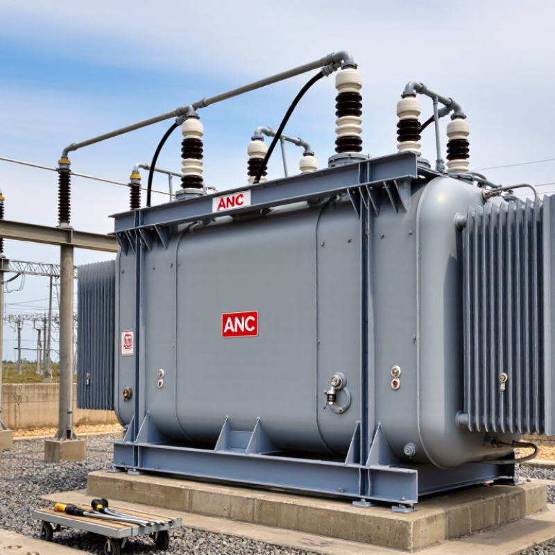
Definition: ANSI/IEEE C57.12.00 Requirements for Three-Phase Oil Transformers
What Is an ANSI Rated Three Phase Oil Transformer?
Definition: ANSI/IEEE C57.12.00 Requirements for Three-Phase Oil Transformers
An ANSI-rated three-phase oil transformer is a liquid-immersed transformer designed around recognized electrical and mechanical requirements. ANSI/IEEE C57.12.00 defines general requirements for liquid-immersed distribution, power, and regulating transformers. It does not simply approve a product by name.
The standard addresses ratings, insulation levels, temperature rise, dielectric performance, construction, and short-circuit strength. It also supports clear nameplate information, including voltage, frequency, impedance, winding connections, and cooling details. During a practical inspection, these values should match the drawings, test reports, and installation conditions. Small discrepancies matter.
Oil provides insulation and transfers heat from the windings to the tank and radiators. Inspectors often check oil level, bushings, grounding points, seals, and visible damage. Testing may include winding resistance, ratio verification, insulation checks, and applied-voltage tests, depending on the specified requirements. The transformer must also withstand expected service conditions, such as ambient temperature and altitude.
C57.12.00 is a foundation, not the entire specification. Related standards, project documents, and purchaser requirements may add details for accessories, sound, testing, or application limits. That distinction is easy to miss. A transformer can meet a general standard and still require engineering review before energization. Careful documentation remains essential.
What Is an ANSI Rated Three Phase Oil Transformer? - Definition: ANSI/IEEE C57.12.00 Requirements for Three-Phase Oil Transformers
| Data Dimension | ANSI/IEEE C57.12.00 Definition or Requirement | Representative Three-Phase Oil Transformer Data | Engineering Notes |
|---|---|---|---|
| Equipment Type | Liquid-immersed transformer covered by the general requirements for transformers, regulators, and reactors. | Three-phase, oil-immersed, two-winding transformer | The standard establishes general electrical, thermal, mechanical, and test requirements; the complete specification may also reference product-specific standards. |
| Applicable Standard | ANSI/IEEE C57.12.00, Standard General Requirements for Liquid-Immersed Distribution, Power, and Regulating Transformers. | ANSI/IEEE C57.12.00: general requirements | A transformer described as ANSI rated should be evaluated against the applicable edition and all referenced standards stated in the purchase specification. |
| Number of Phases | The nameplate and design must identify the phase arrangement and applicable winding connections. | 3 phases; 3-phase, 60 Hz system | Phase sequence, winding connection, neutral availability, and grounding method must be defined by the system design. |
| Rated Frequency | The transformer shall be suitable for its specified operating frequency and tested at the rated frequency unless otherwise stated. | 60 Hz | A 50 Hz or 60 Hz rating should be explicitly specified because frequency affects core flux, losses, heating, and performance. |
| Rated Capacity | The nameplate kVA or MVA rating represents the specified continuous load capability under the stated cooling, temperature, and installation conditions. | 1,000 kVA example rating | Actual capacity must be selected from the required standard kVA range, ambient conditions, altitude, cooling class, and load profile. |
| Primary Voltage | Rated winding voltage and connection shall be identified on the nameplate, together with insulation levels where applicable. | 13.8 kV line-to-line primary | The actual system voltage, maximum system voltage, grounding arrangement, and tap range determine the correct primary design. |
| Secondary Voltage | The secondary rated voltage and winding connection shall be clearly stated for the intended load and system configuration. | 480Y/277 V secondary | “480Y/277 V” indicates 480 V line-to-line and approximately 277 V line-to-neutral on a grounded wye connection. |
| Winding Connection | The transformer identification includes winding connection and phase displacement information required for system compatibility. | Delta primary / grounded-wye secondary; Dyn11 example vector group | The vector designation is an example only; connection and phase displacement must match paralleling, grounding, and protection requirements. |
| Impedance | Percent impedance is a nameplate and performance parameter used for voltage regulation, fault-current calculation, and load sharing. | 5.75% impedance example | The specified impedance tolerance and test method must be confirmed from the applicable standard and procurement documents; the example is not universal. |
| Insulation Level / BIL | Basic impulse insulation level and power-frequency insulation requirements are selected according to the winding voltage class and system insulation coordination. | 15 kV class primary: 95 kV BIL example | BIL is not determined by nominal voltage alone. System overvoltage exposure, grounding, arresters, and applicable tables must be considered. |
| Temperature Rise | The specified average winding and top-liquid temperature-rise limits are based on the selected insulation system, cooling method, and applicable standard requirements. | 65 °C average winding rise; 65 °C top-liquid rise example | Lower-rise designs, such as 55 °C-class designs, may be specified. Ambient temperature and altitude corrections remain important. |
| Cooling Method | The transformer shall identify its cooling class and be capable of carrying the rated load under the specified cooling condition. | ONAN — oil natural, air natural | Larger units may use additional cooling stages such as forced-air operation; the applicable cooling designation must appear in the specification or nameplate data. |
| Tap Arrangement | Tap settings, tap voltage, and tap-changing method shall be defined where voltage adjustment is required. | Five-position de-energized tap changer: ±2.5% and ±5% | The transformer must be de-energized before operating a de-energized tap changer. On-load tap changing is a separate design requirement. |
| Insulating Liquid | The liquid type, quality, compatibility, and handling requirements shall be identified for the transformer design. | Mineral insulating oil, inhibited or uninhibited as specified | Alternative liquids require a design and specification review because dielectric, fire-safety, sealing, and thermal properties differ. |
| Routine and Design Tests | Applicable tests verify electrical performance, insulation integrity, losses, impedance, ratio, polarity or phase relation, and other specified characteristics. | Winding resistance; ratio; polarity or phase relation; no-load loss; excitation current; impedance and load loss; dielectric tests | The exact test list depends on the transformer category, rating, construction, and referenced IEEE test standards. |
| Nameplate Information | The nameplate provides essential identification and operating data needed for installation, operation, maintenance, and protection studies. | kVA; phase; frequency; voltages; connections; taps; impedance; insulation levels; temperature rise; cooling; liquid data | Nameplate values must be checked against approved drawings and field measurements before energization. |
Note: Representative values are illustrative, industry-standard examples rather than universal requirements. Final ratings and test criteria shall be taken from the applicable ANSI/IEEE edition, referenced standards, and the approved project specification.
Let's Build Together


Contact Us: Call 435-563-3503
-OR- Fill in the form below and we will call you back.